
Amp Service
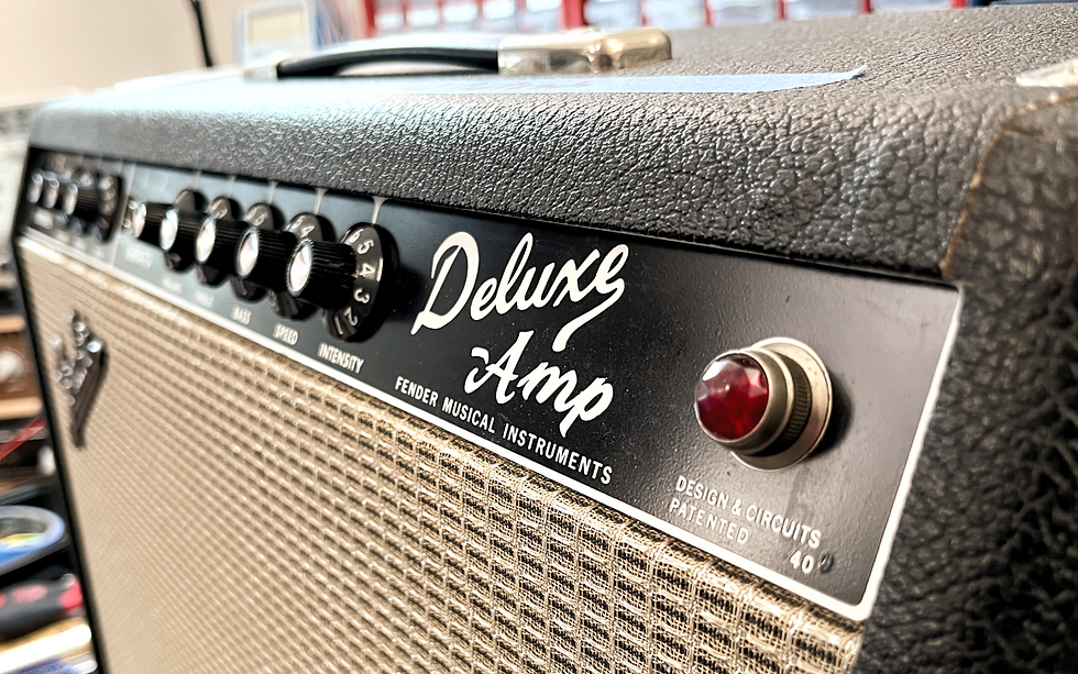
1967 Fender Deluxe Amp
You definitely don't get a piece of jewelery like this on your workbench every day!
Although the big brother "Deluxe Reverb" is much more widespread and popular due to its integrated spring reverb, the "Deluxe" is still a piece of amp history that promises to carry one of the most popular amp sounds of all times.
Equally astonishing was the customer's response to the question: "What's wrong with the poor, little guy?"
The answer was: "Nothing. It's doing great. But it should have a professional check-up to see if everything is still in good condition or if something needs to be overhauled"
Wow, we rarely experience such a responsible handling of a rare piece of amp history. Often the old amps are just played carelessly until they stop working or smoke comes out. Until then there is often more damage than it should have been. So let's get an overview of the amp.


Visual Condition
Is this a re-issue?
In fact, my first thought was, "Is this a vintage amp or a re-issue?". The amp is looking so well. The optical condition can confidently be described as "mint condition". No damage to the tolex and such a charming patina as only 56 Years of aging gracefully can do it.
The front and back panels are also immaculate... no worn or swapped knobs... all hardware is complete and original. It doesn't get any better!
Only the tolex on one of the rear struts has come loose over time and should be glued back together during the service.

Age Assessment
3 ways to date the amp without a screwdriver
Dating Fender amps is, thankfully, comparatively easy, because Fender was very consistent with labels and these are also very well documented. For this you have to don't even disassemble the amp.
Possibility 1: Tube Chart
In every Fender amp there is the so-called "Tube Chart" which reveals what kind of circuit variant was installed in the amp and which tube assembly is intended. In addition, you will find 2 stamped letters on the Tube Chart. The first indicates the year of manufacture and the second the month. Even if the tube chart is a bit battered in the lower area, we recognize "QA". This means January 1967. Here you will find the breakdown of the letter codes.
Possibility 2: Chassis Serial Number
If (as in many old Fender amps) the tube chart is completely missing, it is worth taking a look at the serial number. This is stamped into the chassis on the back of the amp and reads "A06259" on our example. A look into one Serial number overview of old Fender Amps reveals that a Blackface Deluxe with our serial number can be assigned to the year 1967.
Possibility 3: EIA codes
Since you should always check with every vintage Fender amp whether the original transformers are still in it, it is worth taking a look at the stamped 6-digit EIA number. EIA stands for "Electronic Industries Association". In the USA in the 1960s, this assigned a 3-digit number to each manufacturer. A 3-letter system was also used to allow the manufacturer to code the week and year of manufacture. A look at the output transformer gives us the number 606-646, the choke spits out 606-626. 606 stands for the manufacturer "Schuhmacher" (that was before he started his Formula 1 career ;-), and the transformers were wound in the 46th and 26th week of 1966. So that matches the Jan. 1967 reading on the Tube Chart. Even if the choke has obviously been floating around on the shelf for 6 months.
By the way, a look at the speaker reveals the number 465-650 and tells us that it comes from the Oxford company and was built in week 50 of 1966. Here, by the way, you will find a good overview of common EIA codes.
For those who want to know exactly when an amp was built, here is a tip:
Inside the chassis there is usually a date stamped with the exact date of manufacture in plain text. It seems our deluxe saw the light of day on 01/16/67. Unfortunately, many of these stamps have fallen victim to keen attempts to clean them with aggressive cleaning agents over the years.
Ok... you need a screwdriver for this.


First Sound Check
Holy shit!
We can't say it often enough: Please never just plug in an old amp in "unknown" condition to see if it's still working. Bad things can happen there! However, the deluxe was handed over to us by the owner in a known working condition, as he plays it regularly himself. So we can simply test the box without regrets.
Expectation Management:
We expect the amp to still do quite well in principle... but we expect some mains hum, audible hissing, and maybe a little "crustling" or maybe one or another "pop noise".
Vibrato Channel:
So let's start with the Vibrato Channel. Power on... wait... reveal from standby... volume to "5". Hmmm, does the amp even work? You don't hear anything. Volume on "10"... a faint hissing can be heard. Guitar plugged in: Holy shit, that thing is ON!
In short: This is the quietest vintage amp we've ever come across. No hum, very little hiss... no other noise. And the amp sounds phenomenal! Tight, stable... just as one would wish for an excellent "Deluxe".
What does that tell us?
1. The PSU capacitors still seem to filter well.
2. The power tubes still seem to be very well matched.
3. None of the old carbon comb resistors seem to have become "noisy".
4. The coupling capacitors do not seem to be "leaky" yet, otherwise the operating points of the tubes would not be correct and the amp would sound "dirty".
Only the vibrato causes the well-known "ticking" which is known from many old Fender amps. To be more precise, it is almost a "chirping" like a bird. This does not disappear even with "Intensity" set to "0". This was also the only "bug" reported by the owner with a request to fix it. Yep, we can do that!
Normal channel:
The Normal Channel has a bit more noise compared to the Vibrato Channel. Also lower frequency and somewhat modulated. This could be due to carbon comp resistors that have become somewhat "noisy". This sound is typical of this. In order to rule out the responsible preamp tube, we swapped it for a different 7025, and it didn't cange the noise. Ultimately, however, it is "complaining at a very high level" and we have to discuss with the owner whether we should actually "go hunting" here. You actually have to turn the volume to 10 for the noise to be clearly audible. With practical volume settings of 5-6, the noise is virtually imperceptible.
Pots & Jack Sockets:
The pots run fairly quietly, but could do with cleaning with DeoxIT F5. Not a big act. In any case, there is no potentiometer that causes big problems. Top! The jack sockets still work well, but it can be seen that the "normally open" contacts (when no cable is connected) sometimes no longer close properly. Here the contacts should be cleaned during the amp service. This is perfectly normal for a 56 year old amp. No big deal...
Speakers:
The Oxford speaker in the Deluxe still does a very good job. According to the owner, it's been re-coned before, which is a smart move for old, beat-up speakers. It was noticeable that with a low, dying note (e.g. low E on the guitar) faint, persistent distortions could be heard. Here we should check more closely whether the speaker has a little too much "Rub & Buzz" (voice coil rubs against the magnet pot), or whether something is simply resonating mechanically.
Electrical Condition
Please take off your clothes...
So far there is actually no reason why the '67 Deluxe should be in the Tube WorkShop. Apart from the ticking tremolo, there really isn't a true "fault" and the amp sounds outstanding.
But the point here is not to fix a massive problem, but to ensure that the amp will continue to run so well for the next 20 years.
Then the little Deluxe now has to "get naked" and we'll see what we can find "under the hood".

Electrical Condition I
The Tube Set
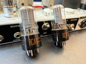
In the amp there are actually 2 old 6V6 from RCA. If these are still in good condition (and they still seem to be due to the low level of background noise) this is the "Holy Grail" for a Deluxe. It doesn't get any better than that. The manufacturer is no longer readable on the rectifier tube, nor on the 12AT7 phase inverter or the 12AX7 in the tremolo. However, you can still guess "Made in Britain" on the GZ34 and the 12AT7 and "USA" on the 12AX7. Since the times when tubes were still being manufactured in the UK and USA are long gone, these are probably not the original tubes, but still some from the "golden age". In the preamp there are 2 12AX7WC from Sovtek. Nothing to complain about, good choice.
Even if the amp seems to play well with this tube set, we would still recommend checking the characteristics and readings on our eTracer measuring system.
Electrical Condition II
Tube sockets
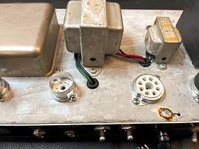
For some reason, all of the original tube sockets in the Deluxe have been replaced with ceramic types. Why this happened remains a mystery. The rest of the amp is in great condition and the chassis shows little corrosion. This means that the amp was not exposed to high humidity for a long time. So why apparently the tube sockets were "over" was not revealed to me.
It's a pity that no high-quality types from Belton with very good contacts and low mechanical tolerances were used here. Unfortunately, the tolerances of the ceramic tube sockets are so generous that, for example, if you use a little force to push in a power tube, you can insert it in the wrong position. Which the coding pin should actually prevent. So watch out!
Otherwise, the exchanged tube sockets are in very good condition and were wired reasonably well without causing a major massacre.


Electrical Condition III
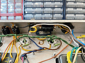
Mains connection & Mains transformer
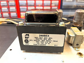
The mains transformer was exchanged for a Hammond 290BEX in the past. Not because the original transformer was defective, but simply because this amp was originally designed for 115V (USA) and the owner was tired of using a step-down transformer. Absolutely understandable. The original mains transformer is still present (which makes collectors happy), but Hammond's 230V replacement is a very good choice. In this context, a 3-pin mains cable with a common ground was also retrofitted. Very good.
We don't quite agree with the installation of the new mains transformer and the mains connection. This was exchanged 1:1 for the old transformer, without considering the fact that electrical safety guidelines have evolved since the 1960s.
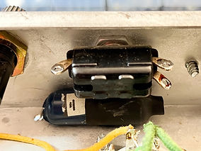
There is still the legendary "death cap" in the circuit.
It comes from the time when there was no separate "grounding". The "death cap" can be switched back and forth between L and N on the mains supply line and leads directly to the housing. Depending on the environment, it was able to suppress high-frequency network interference in one position or another.
Problem:
If the "death cap" becomes low-impedance or even causes a short circuit, it may happen that the mains voltage is present at the amp's housing. We don't want that! Ok, attentive readers now will say: "But wait a minute, a common ground connection was retrofitted, then the FI in the house should blow when that happens!". Well, firstly I don't want to entrust my health to the house electrics and secondly the FI probably only flies in the event of a hard short circuit in the death cap and not yet when it becomes low-resistance.
In this day and age (where there is a common ground connected to the housing) this capacitor just makes no sense at all and should be removed from the circuit for safety reasons.
Other issues:
In our '67 Deluxe, the original mains transformer was replaced with a 230V type without adapting the wiring to current safety standards. E.g. the (well-intentioned) 115V outlet from Fender is still in operation with 230V.... however, there are no devices with a USA plug that require 230V. In addition, this outlet has no grounding. In our opinion, it should be shut down.
Furthermore, the original Fender wiring was retained, with the mains fuse being in the neutral conductor of the mains voltage, which is no longer up to date. Both the fuse and the power switch must be installed on the hot wire and in that exact order. All of this has no effect on the sound and, to be honest, is not really "unsafe" either, but we would still strongly recommend modifying the mains cabling to the current safety standards.
"Better living?"
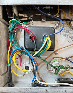
The installation of the Hammond 230V transformer was technically ok and works perfectly, but it was done in a rather "pragmatic" way. Wires that belong together can also be twisted in order to suppress background noise as much as possible, resulting in a tidier picture. The owner has to decide whether this should be left as it is or whether it should be "cleaned up". Ultimately, it's actually pure aesthetics.
Electrical Condition IV
PSU Capacitors
We would have bet a box of beer that a cap job had been done on this amp due to the low level of background noise. It's not like that! After we got the "Doghouse" removed, 4 original Mallory 16uF/450V electrolytic capacitors awaited us and happily shouted out "Hello Mario".
I'm baffled now. In fact, the parts look like they did on day one and still show no signs of leaking electrolyte or "bulging". A quick check of the AC ripple at the first filter node shows a quite typical value even with 5V AC. So the 56-year-old electrolytic capacitors still seem to be working fine.
Dilemma:
And there it is again, the old dilemma with vintage amps and their electrolytic capacitors. To swap or not to swap? On the one hand you can say: "Why swap when the old Mallory's are still okay?". On the other hand, it's just that electrolytic capacitors are devices that are only designed to have a finite lifespan. That's usually 15-20 years. Ok, with good electrolytic capacitors and little use maybe 30 years. But at the age of 56 we are already well past the "best before" date.
It's a bit like yogurt. You can usually eat it even after the best-before date has expired, provided the seal was not broken. Open it, look at it, smell it, try it... if nothing is noticeable, the yoghurt is still ok. You still do that when it's expired 2 weeks... maybe you still do it when it's expired 2 months. When do you get to the point where you would rather throw away the yoghurt as a precaution instead of eating it even if it seems to be ok? After 2 years past expiry date? Everyone has to know that for themselves.
But actually it's not about yoghurt but about capacitors. What I want to say: There is a point where you prefer to exchange old electrolytic capacitors even if they still seem to work well. Simply for the sake of being "safe". At the end of the day, the owner has to decide whether this point has been reached. From a purely technical point of view, the power supply capacitors are still working perfectly.
"What would you recommend?"
... is of course the question that the owner of the amp will ask us directly. Rightly so, the amp is finally with us to be checked by an expert. By the legendary words of Dave Friedman at Tone-Talk: "It depends!"
If the amp is still in absolute original condition and only occasionally played at low volume at home, I would say: "Leave the electrolytic capacitors in. They still seem to work well and in this condition the amp has highest collector value. But pay attention to it whether noises such as increased humming or sporadic cracking and popping noises occur.
If the amp is often played loud (regardless of whether in rehearsals, live or at home on a load box) I would play it safe and make the amp as reliable as possible. And for me, this also includes exchanging 56-year-old power supply capacitors.
In the present Deluxe, I would advise exchanging the electrolytic capacitors. Why?
After replacing the tube sockets and the mains transformer, the amp is no longer in its original condition anyway. An exchange of the power supply electrolytic capacitors does not reduce the collector's value and the plus in security would let me sleep better.


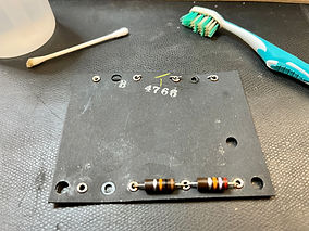
Electrical Condition V
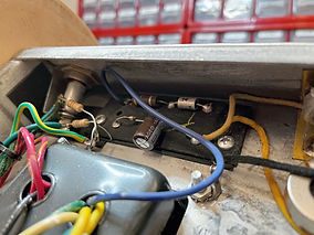
Bias board & Virtual Center Tap
It's not really clear to me why some things have been done on this amp in the past and others have not.
The power supply electrolytic capacitors have not been exchanged so far. But the capacitor of the bias circuit has. In principle, this is a good idea, because if the bias circuit no longer works, it is about as dangerous for the amp as a defective power supply capacitor. But why one and not the other? Anyway, we don't have to understand everything.
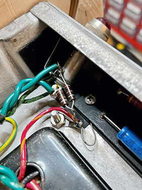
Unfortunately, the work at this point was not "pragmatic" as with the mains transformer, but rather sloppy. The old capacitor was simply snapped out, and then a new radial capacitor was soldered to the legs. A correct, axial type was probably not at hand.
The same applies to the virtual center tap of the heating cables in the immediate vicinity. Again, good idea... badly done!
First of all, for optical reasons, I would use the same carbon comp resistors as in the rest of the amp. Secondly, I find a free-flying wire construction in which not even the too long legs of the resistors were shortened optically simply shameful in such a beautiful amp. Folks... damn it, try a little harder when you're working on a piece of amp history.
My recommendation to the owner would be to correct this optical massacre. Honestly, I'll do it anyway, for free if necessary. I just can't see that...
Electrical Condition VI
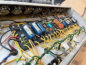
The actual amplifier circuit...
... is also built in our '67 Deluxe onto the typical Fender eyelet board made of wax-soaked hard cardboard. Thank God we are dealing with a 1960s model where the wax was still used moderately. From the 70s Silverface models on, so much wax was often used here that with the dirt of the decades, it is often a sticky layer on the surface which is partially conductive. This leads to the funniest noises and drifted working points. You can also get "fit" again, but it's a lot of work and a huge mess.
So we probably won't have to bother with this, but we will still check the board for leakage currents at a few critical points when checking the circuit.
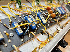
All Originals:
Otherwise there is to report that the complete amplifier circuit is virtually untouched.
We are happy about the complete set of the legendary "Blue Molded" capacitors, which play a significant role in the sound of a vintage Fender amp. These are also known for their longevity. A first quick check revealed that obviously none of the Blue Molded has become "leaky". Top!
Cathode Capacitors:
We were a little bit surprised about the cathode capacitors in the circuit. Here we would have actually expected the orange cardboard rolls from Astron, similar to Mallory's power supply capacitors. However, the solder joints look untouched and original. So it doesn't seem to be a question of later replacements, but to have been installed from the factory.
Here, too, the same question of conscience arises as with the power supply electrolytic capacitors: To swap or not to swap? The cathode capacitors are also electrolytic types with a planned lifespan of around 20 years. Admittedly, these are less safety-critical than the power supply electrolytic capacitors or the bias capacitor. A bad cathode capacitor can make the amp sound like crap... but it can't kill it.
Recommendations:
The circuit should be checked for heavily drifted resistance values and the function of the coupling capacitors. But due to the good performance of the amp, we don't expect any excessive flaws. If the power supply electrolytic capacitors are to be exchanged in the amp, I would recommend doing the cathode electrolytic capacitors at the same time. Then you have mental "peace" when it comes to electrolytic capacitors and don't have to think about it for the next 20 years.
We will also take care of the problem of the "ticking" or "chirping" tremolo when checking the circuit and (hopefully) fix it.
The question remains whether the slightly increased and modulated noise of the "Normal" channel should be chased?


Interim Conclusion
Where are we standing?
So far nothing has been "done" to the amp. The soldering iron has stayed cold so far.
It was about checking a '67 Fender Deluxe, which is in excellent condition, and about to determine what work might be necessary to keep this amp in this condition for the next 20 years.
Here is our list of possible service work:
-
Cosmetics: Gluing the partially detached Tolex
-
Checking the tube set on eTracer Curve Tracer measuring system
-
Removal of the "Death Cap" & Upgrade mains cabling to current standards
-
"Better living" when wiring the replaced mains transformer
-
Exchange of the 56-year-old power supply capacitors for current F&T types
-
"Better living" at the bias circuit & Virtual center tap of the heating lines
-
Check all components of the amplifier circuit & Elimination of the "ticking" in the tremolo
-
Optional: Reduce Normal Channel in noise
-
Cleaning all jack sockets & Pots
-
Final Check & Setting the power amp bias
-
Checking Speaker on Rub & Buzz or localization and fix mechanical noises
Next on the agenda is a consultation with the owner of the amp about which works should be done and which not.
Ready, Steady, Go!
We got the green light...
After consultation with the owner it is clear: We will carry out the full scope of work!
We are always happy to work for people who own a rare vintage amp and are aware of the responsibility to keep it in best condition. This goes beyond the pure sound of the amp, and also includes carrying out necessary modifications, upgrades and maintenance work in a form that is visually and electrically fair to a precious vintage amp, rather than just quickly snapping out a few components and gluing others back on.
Servicing - Part I
The mains wiring...
A corner that often gets little attention because it works... somehow.
Our 67 Deluxe was built at a time, where the safety guidelines were not as pronounced as they are today.
The 2-pin mains connection from the 1960s was first wired to a well-intentioned 115V outlet (other devices were intended to be connected here). The "hot" wire then went through the power switch while the "neutral" wire was connected to the mains fuse. In between, the switchable "death cap" was wired, with which the capacitive housing grounding between the mains and neutral conductors could be switched back and forth. This still works today. Somehow... nowadays we have 3-pin mains connections with a separate earth connection.
The current guidelines require the following:
-
The ground is connected to the chassis on an exclusive terminal. No other ground connections may be made here. This also makes the "death cap" superfluous, which had the function of "capacitively" coupling the housing.
-
The chassis ground connection must have the longest wire length. So if the amp is dropped, and the power cord is ripped out, make sure the ground is disconnected last. Otherwise (theoretically) mains voltage could be applied to the housing without triggering a fuse.
-
The mains conductor must first go through the mains fuse. With Fender amps it should be noted that the mains conductor is wired to the "rear" connection of the fuse holder used. This ensures that you do not accidentally touch the side where the mains voltage is applied when pulling out a defective fuse. With modern fuse holders, you usually don't have to worry about it anymore, but that's how it was back then.
-
The mains conductor can then go through the power switch, which supplies the entire amp with power. As you can see, it's all a bit theoretical, since you can plug in the mains plug either at 0° or at 180°, especially in Europe. This means that either the mains conductor or the neutral conductor can be connected to the mains fuse and power switch. It honestly doesn't make a difference, and I didn't make the rules up either. These were some clever people in standardization authorities who hadn't plugged in a power plug themselves for 10 years... ;-)
No more joking, at the end of the day it is simply a hygiene factor during an amp service to bring the mains wiring up to the current standard. That lets us sleep peacefully, and so does the smart people who came up with the safety rules.
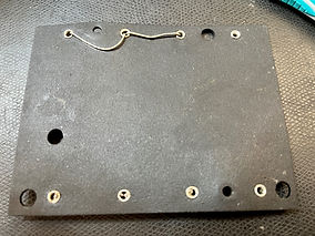
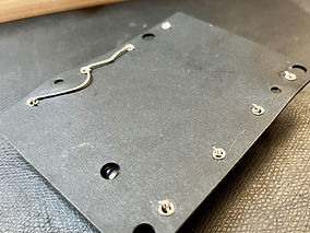
So, first we remove the complete mains wiring and clean all the soldering lugs to have a good starting point for the new wiring.
At the mains supply we can still strip the protective sheathing far enough that we get enough cable length for the mains conductors. Please be very careful. The PVC sheathing of modern power cords cuts like "butter" and you not only cut through the sheathing faster than you think, but also the insulation of the inner conductor. So here: Little force... work your way forward bit by bit. Like filleting a fish.
First we create a "free" ground point for grounding by removing the center tap of the HT voltage that was previously soldered there (it will later go to another ground point) and arranging the grounding wire in a loop. Otherwise, we then carry out the wiring as described above. There is really nothing spectacular to report here.
Oh wait... one thing... maybe:
Of course, you can also twist the neutral conductor of the mains wiring and connect it to the primary winding of the mains transformer with shrink tubing. However, a more elegant solution is to use a soldering lug of the free "ground switch" as a "terminal". Since this no longer has any function after removing the "death cap" anyway, you can use it as a soldering terminal with a clear conscience. Just as a tip...


Servicing - Part II
Mains transformer wiring
Ok, admittedly... this topic is really "unsexy".
You can wire a new mains transformer in 2 ways:
-
The pragmatic one: you solder all the cables correctly and then tie them together with cable ties to form a cable harness that glosses over the chaos a bit.
-
The nice thing: Wires that belong together are twisted and routed to the connections using the shortest possible route. Theoretically, the twisting ensures a slightly lower stray field of the AC lines, but to be honest this is not really decisive for the war at this point. The significantly greater benefit is tidier cabling, which allows clear assignment and facilitates future services. And it just looks nicer too!
At this point we limit ourselves to a before/after picture.
While no "miracles" were performed, we find a wiring that is much more structured and easier to read. Incidentally, we clipped out about 30cm of unneeded cable. You remember: Always keep all lines as short as possible!
Servicing - Part III
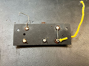
The Bias board.
Yeah, that doesn't sound any more exciting than tidying up the wiring for the mains transformer. But it is. A little at least...
This small, inconspicuous circuit board in the upper left corner of old Fender amps ensures that the power tubes run at the correct operating point or can be adjusted to it.
How does it work with setting the Bias?
Aaawell, to put it very roughly, the control grid of a power tube must be negative compared to the cathode. Otherwise the tube does nothing. Especially in a power amp there are 2 common methods to achieve this:
1. Cathode Bias
A resistor and a capacitor connected in parallel are inserted at the cathode. Together with the tube, this forms a kind of voltage divider. This means that the cathode does not have 0V, but a positive DC voltage potential, which depends on the bias current of the tube and the value of the resistor. Goal achieved: the cathode is positive, the control grid, on the other hand, is at 0V and is therefore more negative than the cathode.
2. Fixed Bias
In this case, the cathode of the tube is grounded. Thus the control grid must be negative. For this purpose, there is a bias circuit in the corresponding amps, which generates a negative voltage either from the high-voltage winding of the mains transformer or from a winding specially provided for this purpose. The necessary components for this are being located on the Bias Board of our 67's Deluxe. This voltage is used as the reference potential for the control grids of the power tubes instead of ground. Eh voilà, also in this case the control grid is again more negative than the cathode.
For general amusement, here is the test question for all prospective amp technicians:
Question: "What is the difference between Cathode Bias and Fixed Bias?"
Answer: "Cathode bias is fixed. Fixed bias, on the other hand, is usually adjustable!"
Now that everyone is completely confused, back to the serious side of life.
What happens if there is a problem here?
The bias board in our Deluxe has the function of generating a negative voltage from a special transformer winding, which causes the power tubes to feel good.
What happens if there is a defect in the bias circuit?
Well, in most cases this means that negative voltage is no longer generated and the power tubes are "fully conducting" with 0V bias. This means that the maximum current flows and the anode plates start to redplate. The power tubes no longer feel good, but go into "suicide mode". Of course we don't want that.
Presumably for exactly this reason, the electrolytic capacitor in the bias circuit has already been replaced in the past. Good idea. A 47uF type was used here instead of the original 25uF capacitor. That's a good idea too, because it smoothes out the bias voltage a bit more. But we wouldn't go any higher, because otherwise the adjustment of the bias voltage would become too sluggish.
Not such a good idea, but rather laziness, was the fact that the old capacitor was simply snapped out and a new one was soldered to the leads. Yes, technically it works... and we also know why it was done. In old Fender amps, the leads from components were often pushed through the eyelets, bent over, and used directly to connect to the next eyelet. So you can't easily get some components out as it probably is connected to another solder point. So the "shortcut" for many technicians is to snap off the leads of the old component and solder the new component there.
It's not pretty, and soldering tin is actually designed to make electrical connections and not to make additional mechanical connections.
Let's do it right:
If you want to do it "right" you have no choice but to remove the entire bias board. The component to be replaced is now removed and the corresponding eyelets are freed from old solder and flux. If legs of the old component were used as a connection to other eyelets, they are welcome to remain, but the ends should be bent around the edge of the eyelet to secure them mechanically. Then the new components come in, here too the ends of the connecting wires are bent around the eyelet to secure them mechanically, and then they are re-soldered with fresh solder.
We also choose a 47uF filter capacitor, but with a 100V withstand voltage and a high quality axial type from Vishay. In this configuration the Elko should have a relaxed life. The original 470 Ohm dropping resistor was still completely ok and will remain in the circuit. Likewise the original rectifier diode.
In the case of the latter, we "shrugged" briefly. Yes, this is an absolutely safety-critical component. Diode broken = no bias = bad things happen. BUT: Firstly, the diodes in Fender amps are not known to fail, and secondly, diodes (unlike electrolytic capacitors) are not components that are designed for a "finite" lifespan. Of course, as with all other components in the amp, you can ask yourself whether it could break. But then you would actually have to replace almost everything in an old amp.
The big difference between electrolytic capacitors and other components is as follows:
With electrolytic capacitors, the question does not arise as to whether they can break. The only question is "when" will they break. This is not the case with other components because they do not have a "best before" date. You know... yoghurt and stuff... see above...
Incidentally, in passing, we also replaced the two free-flying virtual center tap resistors of the heating voltage in this corner with historically correct carbon press types and installed them "properly".


Servicing-Part IV
Power supply electrolytic.
The amp still performed well with the original power supply capacitors. That's why we recommended replacing them, but left the final decision to the owner of the amp.
He decided to exchange the power supply electrolytic capacitors. And this was a very good and far-sighted decision, as we shall see later.
So, "Filter-Cap Service"... how do we do it? As always, there are different options in different quality.
1. "Clip & Glue" Method
Some technicians do it with the power supply capacitors in a similar way to what we have already seen with the capacitors on the bias board. Snap out the old electrolytic capacitors, solder (="glue") the new electrolytic capacitors to the existing connection wires. Done! Ok, so you can do a "cap job" in 15min. carry out. The excuse for working like this is usually: "We want to save costs for the customer. That's the quickest and cheapest way to do it." Yep, right... that's the quickest way. Quite apart from the fact that one has "botched" one of the neuralgic areas of an amp. As said before, soldering is meant to make an electrical connection... not a mechanical one.
2. "J-Hooking"
The old filter caps are simply snapped out, but the connecting wires are left long enough that a loop (= a "J") can then be bent into them. This is also done with the new capacitors, and the two loops are hooked together and then soldered. Mechanically and electrically there is little to complain about with this solution, but it is not really "nice" and looks a bit "tinkered".
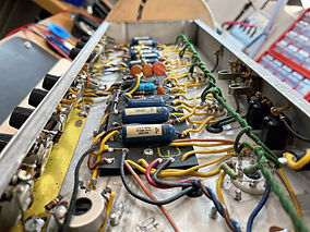
3. "Factory Specs"
Similar to the bias board, we deal with all the circumstances here, such as using the capacitor connection wires as forwarders to other connection points. The filter board has to be removed completely, etc.
But this is the only way to produce an electrical, mechanical and optical standard like "ex works", and this is the method we use on our '67 Deluxe.
The procedure is as follows:
-
Completely remove the filter circuit board
-
Remove old electrolytic capacitors. If connecting wires were used as forwarding, leave them as they are.
-
Clean old solder and flux from all eyelets
-
Bend existing forwarding wires around the eyelets for mechanical security.
-
Insert new capacitors. Also bend the connections around the eyelets for mechanical security
-
Re-installation of the filter board. Attaching all lines and subsequent soldering of the eyelets.
In this scenario, the complete structure is actually stable and functional even before soldering. Soldering only serves to ensure a secure electrical contact. This corresponds exactly to the structure as it was made ex works, but we also mechanically secure the new filter electrolytic capacitors with some silicone.
Of course, the bottom line is that this method takes much longer than "Clip & Glue" and is therefore more expensive for the customer. However, this gives you an electrical and mechanical structure as if the new 15uF filter capacitors from F&T had been installed "ex works". A vintage amp should simply be "value" for us.
A few more words about the replaced components:
-
We measured the original electrolytic capacitors after disassembly, and especially with the first filter electrolytic capacitor (which is exposed to the highest voltage) only half the capacity and a very high ESR value was found. Even if the power supply filtering still did a good job overall, this electrolytic cap was definitely on the way to "dying". Therefore, the owner's decision for a "Cap Service" was spot on.
-
The electrolytic capacitors were exchanged for types from F&T, Made in Germany. This is the best you can currently get, and the upgrade of the dielectric strength from 450V to 500V will also benefit the longevity of the new electrolytic capacitors.
-
The 10k and 27k dropping resistors were still absolutely ok and were left in the circuit.
Servicing - Part V
Cathode-Caps, Inputs, Coupling-Caps & Tremolo.
So, after the power supply and the bias board are in top form again, we dedicate ourselves to the preamp. There are actually very few complaints here. Except for the fact that the Tremolo produces an unmistakable "ticking". We'll fix that.
And we notice that the "Normal" channel is a little more noisy than the "Vibrato channel". Let's see also on.
In addition, we have agreed a "cap service" for the cathode electrolytic capacitors of the preamp together with our customer. Just like the electrolytic capacitors in the power supply, these only have a limited lifespan. Even if these are far less stressed than the power supply electrolytic capacitors, an exchange is recommended after 66 years to make the amp fit for the future again. We remember: Elko's are designed for a service life of approx. 20 years.
But before that, let's take a closer look at the coupling capacitors and input jacks...
Input jacks:
As in virtually every amp, "unused" input jacks make a connection to ground, which ensures that input is shut down and not acting as an antenna for interference.
Over time, an oxide film usually forms on the "closing contacts" of the input sockets, which ensures that they no longer have a solid ground contact if they are not used.
This wasn't a problem in our Fender Deluxe, but we anyway cleaned all the switch contacts on the input sockets. DeoxIt D5 or F5 is recommended for this in combination with a rough piece of cardboard soaked in it. This is used to carefully rub off all switch contacts to remove oxide layers without damaging the surface of the metals. While using sand-paper would work optimally in the short term, it introduces additional problems in the long term as the emery paper will damage the surface of the contacts, opening the door to future corrosion.
Coupling Capacitors:
As already suspected from our first measurements, the condition of the "Blue Molded" capacitors is confirmed as "Good" even on closer inspection. None of the nice capacitors have "leaked" over time and let DC voltage through. That's "Outstanding". The "Blue Molded" capacitors of old Fender amps are not only of very high quality, but also play a large part in the sound of these amps. Even if there are replacement types nowadays that come close in terms of sound, it is always a pleasure when an old amp can "live on" with its original components.
Cathode Capacitors:
There is nothing spectacular to report here, except that we were a little surprised to find no orange cardboard tubes from Astron, but rather potted, black types from an unknown manufacturer (one guess would be Cornell Dubilier). Anyway, there are currently no really mechanically suitable replacement types for both in the form of 25uF/25V double electrolytic capacitors.
This isn't too tragic, however, since two individual 25uF/25V electrolytic capacitors were quickly made into a dual electrolytic capacitor. This is common practice. At Fender Amps, we like to use the Bipolar types from Tube Amp Doctor for this, as they support very nice overtones and spatiality with their smooth foil.
And oh yes... if we're already unsoldering the cathode electrolytic capacitors, we'll also measure whether the cathode resistors are still within their specification or whether they should be replaced. In this case: All cathode resistances are still tiptop!
Calming down the Normal Channel:
Well, we're already banging around in the preamp, so we're chasing this problem as well. As already written, the noise was not excessively high, but compared to the vibrato channel, it is noticeable that the noise in the normal channel is significantly "dirtier" and sounds more like flushing the toilet. Sorry for the comparison, but that's the way it is. Normal, thermal noise = Gently turned on faucet. Sdirty noise = toilet flushing.
After we have swapped the preamp tube in question (and ruled it out as the cause), we take a closer look at the anode resistors. They were actually our "prime suspects" from the start.
And indeed, the "toilet flushing" disappears after we swapped the 100k anode resistors of the normal channel and the 100k resistor in the tone control network. All of these 3 resistors are directly across the high voltage and the old carbon press types are known to get "noisy" here over time. Why this was only the case in the normal channel remains unclear, but one explanation could be that the amp was mainly played over this channel in the past. However. New resistors (of course historically correct carbon press types), and the noise is a pure, soothing, thermal noise which is also very good for sleeping. Just put the deluxe next to the bed and turn up the volume, very soothing!
The ticking tremolo:
Ok... Fender incorrectly refers to the tremolo as "vibrato" while they call the vibrato on their guitars "tremolo". It would be the other way around. But hey: who can look past those old European terms for volume modulation and frequency modulation? Fender certainly didn't.
Anyway, so in the Deluxe we have a vibrato (which is actually a tremolo) and it makes noise. It ticks. Even if "Intensity" is 0. This is a well-known phenomenon of old Fender amps. So well known that Fender has published its own service bulletin.
Where does the ticking come from?
Well, in the common Fender tremolo circuit with a small neon lamp and an LDR (= Light Dependent Resistor), the neon lamp is subjected to a fairly steep-edged signal to make it pulsate. So far not bad. However, if these lines are twisted tightly and neatly with signal lines, it can happen that these steep-edged signals scatter into the audio lines.
As a "fix", Fender suggests untwisting the lines and laying them differently, and/or integrating a 10nF capacitor into the control of the neon lamp to smooth out the steep flanks. Experience has shown that this capacitor can also be somewhat larger.
So before we destroy the beautiful, original wiring of our Deluxe, let's try the capacitor trick first. And bingo! With a 22nF capacitor we were able to completely eliminate the "ticking". So not only "improve", but it has completely disappeared with this intervention. This is very good as it means we don't have to tear apart the original wiring.
Check of all remeining components:
The cathode electrolytic capacitors have been renewed. The cathode resistances are still good. We have replaced noisy anode resistors. The tremolo no longer ticks. Coupling capacitors are checked for "leakage". A final check of all remaining components remains. These are still absolutely ok and can stay in the amp.
Happy days!


To be continued
Stay tuned...
As soon as we have agreed with the owner of the amp which service work will actually be carried out, we will continue here...